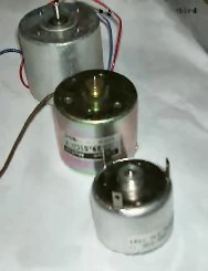
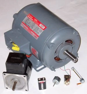
Electric motors of various sizes.
An electric motor converts electrical energy into mechanical motion.
Device references[]
The reverse task, that of converting mechanical motion into electrical energy, is accomplished by a generator or dynamo. In many cases the two devices differ only in their application and minor construction details, and some applications use a single device to fill both roles. For example, traction motors used on locomotives often perform both tasks if the locomotive is equipped with dynamic brakes.
Principle of operation[]
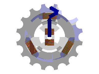
Rotating magnetic field as a sum of magnetic vectors from 3 phase coils.
Most electric motors work by electromagnetism, but motors based on other electromechanical phenomena, such as electrostatic forces and the piezoelectric effect, also exist. The fundamental principle upon which electromagnetic motors are based is that there is a mechanical force on any wire when it is conducting electricity while contained within a magnetic field. The force is described by the Lorentz force law and is perpendicular to both the wire and the magnetic field.
Most magnetic motors are rotary, but linear types also exist. In a rotary motor, the rotating part (usually on the inside) is called the rotor, and the stationary part is called the stator. The rotor rotates because the wires and magnetic field are arranged so that a torque is developed about the rotor's axis. The motor contains electromagnets that are wound on a frame. Though this frame is often called the armature, that term is often erroneously applied. Correctly, the armature is that part of the motor across which the input voltage is supplied. Depending upon the design of the machine, either the rotor or the stator can serve as the armature.
DC motors[]
One of the first electromagnetic rotary motors was invented by Michael Faraday [1] in 1821 and consisted of a free-hanging wire dipping into a pool of mercury.
A permanent magnet was placed in the middle of the pool. When a current was passed through the wire, the wire rotated around the magnet, showing that the current gave rise to a circular magnetic field around the wire. This motor is often demonstrated in school physics classes, but brine is sometimes used in place of the toxic mercury. This is the simplest form of a class of electric motors called homopolar motors. A later refinement is the Barlow's Wheel [2].
Another early electric motor design used a reciprocating plunger inside a switched solenoid; conceptually it could be viewed as an electromagnetic version of a two stroke internal combustion engine.
The modern DC motor was invented by accident in 1873, when Zénobe Gramme
[3] connected a spinning dynamo to a second similar unit, driving it as a motor.
The classic DC motor has a rotating legature in the form of an electromagnet.
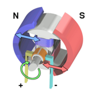
A rotary switch called a commutator reverses the direction of the electric current twice every cycle, to flow through the armature so that the poles of the electromagnet push and pull against the permanent magnets on the outside of the motor. As the poles of the armature electromagnet pass the poles of the permanent magnets, the commutator reverses the polarity of the armature electromagnet. During that instant of switching polarity, inertia keeps the classical motor going in the proper direction. (See the diagrams below.)
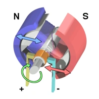
A simple DC electric motor. When the coil is powered, a magnetic field is generated around the armature. The left side of the armature is pushed away from the left magnet and drawn toward the right, causing rotation.
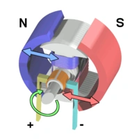
The armature continues to rotate.

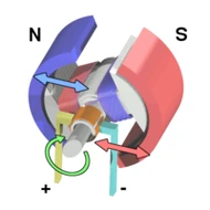
When the armature becomes horizontally aligned, the commutator reverses the direction of current through the coil, reversing the magnetic field. The process then repeats.
Wound field DC motor[]
The permanent magnets on the outside (stator) of a DC motor may be replaced by electromagnets. By varying the field current it is possible to alter the speed/torque ratio of the motor. Typically the field winding will be placed in series (series wound) with the armature winding to get a high torque low speed motor, in parallel (shunt wound) with the armature to get a high speed low torque motor, or to have a winding partly in parallel, and partly in series (compound wound) for a balance that gives steady speed over a range of loads. Further reductions in field current are possible to gain even higher speed but correspondingly lower torque, called "weak field" operation.
Speed control[]
Generally speaking the rotational speed of a DC motor is proportional to the voltage applied to it, and the torque is proportional to the current. Speed control can be achieved by variable battery tappings, variable supply voltage, resistors or electronic controls. The direction of a wound field DC motor can be changed by reversing either the field or armature connections but not both, this is commonly done with a special set of contactors (direction contactors).
Effective voltage can be varied by inserting a series resistor or by an electronically-controlled switching device made of thyristors,transistors, or, historically, mercury arc rectifiers. In a circuit known as a chopper, the average voltage applied to the motor is varied by switching the supply voltage very rapidly. As the "on" to "off" ratiois varied to alter the average applied voltage, the speed of the motor varies. The rapid switching wastes less energy than series resistors. Output filters smooth the average voltage applied to the motor and reduce motor noise.
Since the series-wound DC motor develops its highest torque at low speed, it is often used in traction applications such as electric locomotives, and trams.
Universal motors[]
A variant of the wound field DC motor is the universal motor. The name derives from the fact that it may use AC or DC supply current, although in practice they are nearly always used with AC supplies. The principle is that in a wound field DC motor the current in both the field and the armature (and hence the resultant magnetic fields) will alternate (reverse polarity) at the same time, and hence the mechanical force generated is always the same. In practice the motor must be specially designed to cope with the AC current (impedance must be taken into account), and the resultant motor is generally less efficient than an equivalent pure DC motor. The maximum output of universal motors is limited, and motors exceeding one kilowatt are rarely operated on commerical power frequency.
The advantage of the universal motor is that AC supplies may be used on motors which have the typical characteristics of DC motors, specifically high starting torque and very compact design if high running speeds are used. The negative aspect is the maintenance and short life problems caused by the commutator. As a result such motors are usually used in AC devices such as food mixers and power tools which are only used intermittently. Continuous speed control of a universal motor running on AC is very easily accomplished using a thyristor circuit while stepped speed control can be accomplished using multiple taps on the field coil. Household blenders that advertise many speeds frequently combine a field coil with several taps and a diode that can be inserted in series with the motor (causing the motor to run on half-wave DC with half the RMS voltage of the AC power line).
Unlike AC motors, universal motors can easily exceed one revolution per cycle of the mains current. This makes them useful for appliances such as blenders, vacuum cleaners, and hair dryers where high-speed operation is desired. Many vacuum cleaner and weed trimmer motors will exceed 10,000 RPM, Dremel and other similar miniature grinders will often exceed 30,000 RPM. A universal motor allowed to operate with no mechanical load will overspeed, which may damage it.
With the very low cost of semiconductor rectifiers, some applications that would have previously used a universal motor now use a pure DC motor, usually with a permanent magnet field. This is especially true if the semiconductor circuit is also used for variable-speed control.
The advantages of the universal motor and alternating-current distribution made installation of a low-frequency traction current distribution system economical for some railway installations.
AC motors[]
A typical AC motor consists of two parts:
- An outside stationary stator having coils supplied with AC current to produce a rotating magnetic field, and;
- An inside rotor attached to the output shaft that is given a torque by the rotating field.
There are two fundamental types of AC motor depending on the type of rotor used:
- The synchronous motor, which rotates exactly at the supply frequency or a submultiple of the supply frequency, and;
- The induction motor, which turns slightly slower, and typically (though not necessarily always) takes the form of the squirrel cage motor.
The rotating magnetic field principle, though commonly credited to Nikola Tesla in 1882 or thereabouts, was employed by scientists such as Michael Faraday and James Clerk Maxwell in the 1820s. Tesla, however, exploited the principle to design a unique two-phase induction motor in 1883. Michael von Dolivo-Dobrowlsky invented the first modern three-phase "cage-rotor" in 1890. Introduction of the motor from 1888 onwards initiated what is known as the Second Industrial Revolution, making possible the efficient generation and long distance distribution of electrical energy using the alternating current transmission system, also of Tesla's invention (1888)[4]. The first successful commercial three phase generation and long distance transmission system was designed by Almerian Decker at Mill Creek No. 1 [5] in Redlands California.[6]
Three-phase AC induction motors[]
Three phase AC induction motors rated 1 Hp (750 W) and 25 W with small motors from CD player, toy and CD/DVD drive reader head traverse
For higher-power applications where a polyphase electrical supply is available, the three-phase (or polyphase) AC induction motor is used. The phase differences between the three phases of the polyphase electrical supply create a rotating electromagnetic field in the motor.
Through electromagnetic induction, the rotating magnetic field induces a current in the conductors in the rotor, which in turn sets up a counterbalancing magnetic field that causes the rotor to turn in the direction the field is rotating. The rotor must always rotate slower than the rotating magnetic field produced by the polyphase electrical supply; otherwise, no counterbalancing field will be produced in the rotor.
Induction motors are the workhorses of industry and motors up to about 500 kW in output are produced in highly standardized frame sizes, making them nearly completely interchangeable between manufacturers (although European and North American standard dimensions are different). Very large synchronous motors are made up to tens of thousands of kilowatts output, for pipeline compressors and wind-tunnel drives.
There are two types of rotors used in induction motors.
Squirrel Cage rotors: Most common AC motors use the squirrel cage rotor, which will be found in virtually all domestic and light industrial alternating current motors. The squirrel cage takes its name from its shape - a ring at either end of the armature, with bars connecting the rings running the length of the rotor. It is typically cast aluminum poured between the iron laminates of the rotor, and usually only the end rings will be visible. The vast majority of the rotor currents will flow through the bars rather than the higher-resistance and usually varnished laminates. Very low voltages at very high currents are typical in the bars and rings; high efficiency motors will often use cast copper in order to reduce the resistance in the rotor.
In operation, the squirrel cage motor may be viewed as a transformer with a rotating secondary - when the rotor is not rotating in sync with the magnetic field, large rotor currents are induced; the large rotor currents magnetize the rotor and interact with the stator's magnetic fields to bring the rotor into synchronization with the stator's field. An unloaded squirrel cage motor at synchronous speed will only consume electrical power to maintain rotor speed against friction and resistance losses; as the mechanical load increases, so will the electrical load - the electrical load is inherently related to the mechanical load. This is similar to a transformer, where the primary's electrical load is related to the secondary's electrical load.
This is why, as an example, a squirrel cage blower motor may cause the lights in a home to dim as it starts, but doesn't dim the lights when its fanbelt (and therefore mechanical load) is removed. Furthermore, a stalled squirrel cage motor (overloaded or with a jammed shaft) will consume current limited only by circuit resistance as it attempts to start; overheating and failure will be the result.
A common type of squirrel cage motor is a shaded pole motor, found in most inexpensive low-noise and low-torque applications like fans. Shaded pole motors are inherently inefficient, and most incorporate some form of impedance protection to limit stalled current. With the exception of shaded pole motors, most squirrel cage motors are extremely efficient.
Virtually every washing machine, dishwasher, standalone fan, record player, etc. uses some variant of a squirrel cage motor.
Wound Rotor: An alternate design, called the wound rotor, is used when variable speed is required. In this case, the rotor has the same number of poles as the stator and the windings are made of wire, connected to slip rings on the shaft. Carbon brushes connect the slip rings to an external controller such as a variable resistor that allows changing the motor's slip rate. In certain high-power variable speed wound-rotor drives, the slip-frequency energy is captured, rectified and returned to the power supply through an inverter.
Compared to squirrel cage rotors, wound rotor motors are expensive and require maintenance of the slip rings and brushes, but they were the standard form for variable speed control before the advent of compact power electronic devices. Transistorized inverters with variable frequency drive can now be used for speed control and wound rotor motors are becoming less common. (Transistorized inverter drives also allow the more-efficient three-phase motors to be used when only single-phase mains current is available.)
Several methods of starting a polyphase motor are used. Where the large inrush current and high starting torque can be permitted, the motor can be started across the line, by applying full line voltage to the terminals. Where it is necessary to limit the starting inrush current (where the motor is large compared with the short-circuit capacity of the supply), reduced voltage starting using either series inductors, an autotransformer, thyristors, or other devices are used. A technique sometimes used is star-delta starting, where the motor coils are initially connected in wye for acceleration of the load, then switched to delta when the load is up to speed. Transistorized drives can directly vary the applied voltage as required by the starting characteristics of the motor and load.
This type of motor is becoming more common in traction applications such as locomotives, where it is known as the asynchronous traction motor.
The speed of the AC motor is determined primarily by the frequency of the AC supply and the number of poles in the stator winding, according to the relation:

where
- Ns = Synchronous speed, in revolutions per minute
- F = AC power frequency
- p = Number of poles per phase winding
Actual RPM for an induction motor will be less than this calculated synchronous speed by an amount known as slip that increases with the torque produced. With no load the speed will be very close to synchronous. When loaded, standard motors have between 2-3% slip, special motors may have up to 7% slip, and a class of motors known as torque motors are rated to operate at 100% slip (0 RPM/full stall).
The slip of the AC motor is calculated by:

where
- Nr = Rotational speed, in revolutions per minute.
- S = Normalised Slip, 0 to 1.
As an example, a typical four-pole motor running on 60 Hz might have a nameplate rating of 1725 RPM at full load, while its calculated speed is 1800.
The speed in this type of motor has traditionally been altered by having additional sets of coils or poles in the motor that can be switched on and off to change the speed of magnetic field rotation. However, developments in power electronics mean that the frequency of the power supply can also now be varied to provide a smoother control of the motor speed.
Three-phase AC synchronous motors[]
If connections to the rotor coils of a three-phase motor are taken out on slip-rings and fed a separate field current to create a continuous magnetic field (or if the rotor consists of a permanent magnet), the result is called a synchronous motor because the rotor will rotate in synchronism with the rotating magnetic field produced by the polyphase electrical supply.
A synchronous motor can also be used as an alternator.
Nowadays, synchronous motors are frequently driven by transistorized variable frequency drives. This greatly eases the problem of starting the massive rotor of a large synchronous motor. They may also be started as induction motors using a squirrel-cage winding that shares the common rotor: once the motor reaches synchronous speed, no current is induced in the squirrel-cage winding so it has little effect on the synchronous operation of the motor, aside from stabilizing the motor speed on load changes.
Synchronous motors are occasionally used as traction motors; the TGV may be the best-known example of such use.
Single-phase AC induction motors[]
A common single-phase motor is the shaded-pole motor, which is used in devices requiring low torque, such as electric fans or other small household appliances. In this motor, small single-turn copper "shading coils" create the moving magnetic field. Part of each pole is encircled by a copper coil or strap; the induced current in the strap opposes the change of flux through the coil (Lenz's Law), so that the maximum field intensity moves across the pole face on each cycle.
Another common single-phase AC motor is the split-phase induction motor, commonly used in major appliances such as washing machines and clothes dryers. Compared to the shaded pole motor, these motors can generally provide much greater starting torque by using a special startup winding in conjunction with a centrifugal switch.
In the split phase motor, the startup winding is designed with a higher resistance than the running winding. This creates an LR circuit which slightly shifts the phase of the current in the startup winding. When the motor is starting, the startup winding is connected to the power source via a set of spring-loaded contacts pressed upon by the not-yet-rotating centrifugal switch. The starting winding is wound with fewer turns of smaller wire than the main winding, so it has a lower inductance (L) and higher resistance (R). The lower L/R ratio creates a small phase shift, not more than about 30 degrees, between the flux due to the main winding and the flux of the starting winding. The starting direction of rotation may be reversed simply by exchanging the connections of the startup winding relative to the running winding.
The phase of the magnetic field in this startup winding is shifted from the phase of the mains power, allowing the creation of a moving magnetic field which starts the motor. Once the motor reaches near design operating speed, the centrifugal switch activates, opening the contacts and disconnecting the startup winding from the power source. The motor then operates solely on the running winding. The starting winding must be disconnected since it would increase the losses in the motor.
In a capacitor start motor, a starting capacitor is inserted in series with the startup winding, creating an LC circuit which is capable of a much greater phase shift (and so, a much greater starting torque). The capacitor naturally adds expense to such motors.
Another variation is the Permanent Split-Capacitor (PSC) motor. This motor operates similarly to the capacitor-start motor described above, but there is no centrifugal starting switch and the second winding is permanently connected to the power source. PSC motors are frequently used in air handlers, fans, and blowers and other cases where a variable speed is desired. By changing taps on the running winding but keeping the load constant, the motor can be made to run at different speeds.
Single-phase AC synchronous motors[]
Small single-phase AC motors can also be designed with magnetized rotors (or several variations on that idea). The rotors in these motors do not require any induced current so they do not slip backward against the mains frequency. Instead, they rotate synchronously with the mains frequency. Because of their highly accurate speed, such motors are usually used to power mechanical clocks, audio turntables, and tape drives; formerly they were also much used in accurate timing instruments such as strip-chart recorders or telescope drive mechanisms. The shaded-pole synchronous motor is one version.
Because inertia makes it difficult to instantly accelerate the rotor from stopped to synchronous speed, these motors normally require some sort of special feature to get started. Various designs use a small induction motor (which may share the same field coils and rotor as the synchronous motor) or a very light rotor with a one-way mechanism (to ensure that the rotor starts in the "forward" direction).
Stepper motors[]
- Main article: Stepper motor
Closely related in design to three-phase AC synchronous motors are stepper motors, where an internal rotor containing permanent magnets or a large iron core with salient poles is controlled by a set of external magnets that are switched electronically. A stepper motor may also be thought of as a cross between a DC electric motor and a solenoid. As each coil is energized in turn, the rotor aligns itself with the magnetic field produced by the energized field winding. Unlike a synchronous motor, in its application, the motor may not rotate continuously; instead, it "steps" from one position to the next as field windings are energized and deenergized in sequence. Depending on the sequence, the rotor may turn forwards or backwards.
Simple stepper motor drivers entirely energize or entirely deenergize the field windings, leading the rotor to "cog" to a limited number of positions; more sophisticated drivers can proportionally control the power to the field windings allowing the rotors to position "between" the "cog" points and thereby rotate extremely smoothly. Computer controlled stepper motors are one of the most versatile forms of positioning systems, particularly when part of a digital servo-controlled system.
Brushless DC motors[]
- Main article: Brushless DC electric motor
Many of the limitations of the classic commutator DC motor are due to the need for brushes to press against the commutator. This creates friction. At higher speeds, brushes have increasing difficulty in maintaining contact. Brushes may bounce off the irregularities in the commutator surface, creating sparks. This limits the maximum speed of the machine. The current density per unit area of the brushes limits the output of the motor. The imperfect electric contact also causes electrical noise. Brushes eventually wear out and require replacement, and the commutator itself is subject to wear and maintenance. The commutator assembly on a large machine is a costly element, requiring precision assembly of many parts.
These problems are eliminated in the brushless motor. In this motor, the mechanical "rotating switch" or commutator/brushgear assembly is replaced by an external electronic switch synchronised to the motor's position. Brushless motors are typically 85-90% efficient whereas DC motors with brushgear are typically 10% less efficient.
Midway between ordinary DC motors and stepper motors lies the realm of the brushless DC motor. Built in a fashion very similar to stepper motors, these often use a permanent magnet external rotor, three phases of driving coils, one or more Hall effect devices to sense the position of the rotor, and the associated drive electronics. The coils are activated, one phase after the other, by the drive electronics as cued by the signals from the Hall effect sensors. In effect, they act as three-phase synchronous motors containing their own variable frequency drive electronics.
Brushless DC motors are commonly used where precise speed control is necessary, computer disk drives or in video cassette recorders the spindles within CD, CD-ROM (etc.) drives, and mechanisms within office products such as fans, laser printers and photocopiers. They have several advantages over conventional motors:
- Compared to AC fans using shaded-pole motors, they are very efficient, running much cooler than the equivalent AC motors. This cool operation leads to much-improved life of the fan's bearings.
- Without a commutator to wear out, the life of a DC brushless motor can be significantly longer compared to a DC motor using brushes and a commutator. Commutation also tends to cause a great deal of electrical and RF noise; without a commutator or brushes, a brushless motor may be used in electrically sensitive devices like audio equipment or computers.
- The same Hall effect devices that provide the commutation can also provide a convenient tachometer signal for closed-loop control (servo-controlled) applications. In fans, the tachometer signal can be used to derive a "fan okay" signal.
- The motor can be easily synchronized to an internal or external clock, leading to precise speed control.
Modern DC brushless motors range in power from a fraction of a watt to many kilowatts. Larger brushless motors up to about 100 kW rating are used in electric vehicles. They also find significant use in high-performance electric model aircraft.
Coreless DC motors[]
A coreless DC motor is a specialized form of a brush DC motor. Optimized for rapid acceleration, these motors have a rotor that is constructed without any iron core. The rotor can take the form of a winding-filled cylinder inside the stator magnets, a basket surrounding the stator magnets, or a flat pancake (possibly formed on a printed wiring board) running between upper and lower stator magnets. The windings are typically stabilized by being impregnated with epoxy resins.
Because the rotor is much lighter in weight (mass) than a conventional rotor formed from copper windings on steel laminations, the rotor can accelerate much more rapidly, often achieving a mechanical time constant under 1 ms. This is especially true if the windings use aluminum rather than the heavier copper. But because there is no metal mass in the rotor to act as a heat sink, even small coreless motors must often be cooled by forced air.
These motors were commonly used to drive the capstan(s) of magnetic tape drives and are still widely used in high-performance servo-controlled systems.
Linear motors[]
A linear motor is essentially an electric motor that has been "unrolled" so that instead of producing a torque (rotation), it produces a linear force along its length by setting up a traveling electromagnetic field.
Linear motors are most commonly induction motors or stepper motors. You can find a linear motor in a maglev (Transrapid) train, where the train "flies" over the ground.
See also[]
Components:
- Centrifugal switch
- Commutator (electric)
- Slip ring
Scientists and engineers:
- Ottó Bláthy
- Thomas Edison
- Frank J. Sprague
- Nikola Tesla
- George Westinghouse
Applications:
- Table saw
- Electric vehicle
- Power factor correction
Other:
- Electrical element
- Electrical generator
- Electronics topics
- Technologies
- Maximum power theorem
- Motor
- Motor-generator
- Motor controller
- Propulsion method
- Single phase electric power
External links[]
- Electric Motors and Generators, explainations with animations from the University of New South Wales.
Textbooks[]
- Shanefield D. J., Industrial Electronics for Engineers, Chemists, and Technicians, William Andrew Publishing, Norwich, NY, 2001. A self-teaching textbook that briefly covers electric motors, transformers, speed controllers, wiring codes and grounding, transistors, digital, etc. Easy to read and understand, up to an elementary level on each subject, not a suitable reference book for technologists already working in any of those fields.
- Fitzgerald/Kingsley/Kusko (Fitzgerald/Kingsley/Umans in later years), *Electric Machinery, classic text for junior and senior electrical engineering students. Originally published in 1952, 6th edition published in 2002. Authors still listed as Fitzgerald/Kingsley/Umans although Fitzgerald and Kingsley are now deceased.
- B. R. Pelly, "Thyristor Phase-Controlled Converters and Cycloconverters: Operation, Control, and Performance" (New York: John Wiley, 1971).
References[]
- Donald G. Fink and H. Wayne Beaty, Standard Handbook for Electrical Engineers, Eleventh Edition, McGraw-Hill, New York, 1978, ISBN 007020974X.
- Edwin J. Houston and Arthur Kennelly, Recent Types of Dynamo-Electric Machinery, copyright American Technical Book Company 1897, published by P.F. Collier and Sons New York, 1902
| This page uses Creative Commons Licensed content from Wikipedia (view authors). | 
|