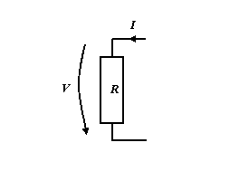
Ohm's law, named after its discoverer Georg Ohm [1] [1], states that the potential difference between two points, or equivalently the voltage drop from one point to a second point, usually designated by U or V, of a device capable of conducting an electrical current and the current I flowing through the device are proportional at a given temperature:

The equation contains the proportionality constant R, which is the electrical resistance of the device.
The unit[]
The unit of resistance is the ohm. The ohm is a unit of measure derived from more basic units of measure. An ohm is equal to a volt per ampere, or a (volt sec)/coulomb. The inverse of resistance, 1/R, is conductivity or electrical conductance, and its SI unit is the siemens.
Description[]
A conduction path in an electrical circuit comprises one or more conductors (i.e. wires having minimal resistance) and/or one or more electrical devices, collectively called circuit elements. Conductors and devices are electrically connected in a way that achieves a desired electrical objective. Devices in electrical circuits that introduce electrical resistance in a conduction path are called resistors. There are many circuit elements whose primary electrical function is distinctly different from that of resistors, yet they also have significant, and often an undesired amount of, electrical resistance (e.g. inductors). Resistive circuit elements are one route by which electric power is lost in an electrical circuit. Usually the power loss is in the form of generating heat or radiating electromagnetic energy.
Overview[]
The law is strictly true only for resistors whose resistance does not depend on the applied voltage. Such resistors are called ohmic or ideal resistors, or ohmic devices. Fortunately, the conditions where Ohm's law holds are very common. Unfortunately, "real world" resistors have a limited range over which V is linearly proportional (i.e. R is constant) to I. At some level of applied voltage, the device will open or short, for example, by burning up or arcing. Further, the voltage across any real resistor, and the current through a real resistor, measured with sufficiently high resolution and over an appropriately selected period of time, fluctuate randomly (when the resistor is at a temperature above absolute zero, i.e. under all real world conditions) with an rms (root mean square) voltage proportional to, or an rms current inversely proportional to, the square root of R. This is known as Johnson noise, or thermal noise.
Some authors apply the relation to non-ohmic devices, but in this case R depends on V and is no longer a constant of proportionality and should not therefore be called "resistance". To check whether a given device is ohmic or not, one plots V versus I and checks that the curve is a straight line or not. The Ohm's law equation is often stated as

in part because that is the variation commonly used with resistors.
Physics[]
Physicists often use the continuum form of Ohm's Law:

where J is the current density (current per unit area), σ is the conductivity (which can be a tensor in anisotropic materials) and E is the electric field. The common form used in circuit design is the macroscopic, averaged-out version.
The equation above is only valid in the reference frame of the conducting material. If the material is moving at velocity v relative to a magnetic field B, a term must be added as follows

The analogy to the Lorentz force [2] is obvious, and in fact Ohm's law can be derived from the Lorentz force and the assumption that there is a drag on the charge carriers proportional to their velocity.
Ohm's law can be considered to be simply the definition of resistance in terms of voltage and current. The physical significance of the law is that in many cases the resistance of a component is not a function of the applied voltage. There are exceptions, of course, such as diodes, which have a non-linear current-voltage relationship. A perfect metal lattice would have no resistivity, but a real metal has crystallographic defects, impurities, multiple isotopes, and thermal motion of the atoms. Electrons scatter from all of these, resulting in resistance to their flow.
Electrical and electronic engineering[]
Many engineers use Ohm's Law every working day. One can not be a functioning electrical engineer without understanding this law intimately. Virtually all electronic circuits have resistive elements which are much more often than not considered ideal ohmic devices, i.e. they obey Ohm's Law. From the engineer's point of view, resistors (devices that "resist" the flow of electrical current) develop a voltage across their terminal conductors (e.g. the two wires emerging from the device) proportional to the amount of current flowing through the device.
More specifically, the voltage measured across a resistor at a given instant is strictly proportional to the current passing through the resistor at that instant. When a functioning electrical circuit drives a current I, measured in amperes, through a resistor of resistance R, the voltage that develops across the resistor is I R, the value of R serving as the proportionality factor. Thus resistors act like current to voltage convertors (just as springs act like displacement to force convertors). Similarly, resistors act like voltage to current convertors when a desired voltage is established across the resistor because a current I equal to 1/R times V must be flowing through the resistor. That current must have been supplied by a circuit element functioning as a current source and it must be passed on to a circuit element that serves as a current sink.
The DC resistance of a resistor is always a positive quantity, and the current flowing through a resistor generates heat in the resistor. Voltages can be either positive or negative, and are always measured with respect to a reference point. When we say that a point in a cirucit has a certain voltage, it is understood that this voltage is really a voltage difference (a two terminal measurement) and that there is an understood, or explicitly stated, reference point, often called ground. Currents can be either positive or negative, the sign of the current indicating the direction of current flow. Current flow in a wire consists of the slow drift of electrons due to the influence of a voltage established between two points on the wire.
Hydraulic analogy[]
While the terms voltage, current and resistance are fairly intuitive terms, beginning students of electrical engineering might find the analog terms for water flow helpful. Water pressure, typically measured in pounds per square inch, is the analog of voltage because establishing a water pressure difference between two points along a (horizontal) pipe causes water to flow. Water flow rate, as in gallons of water per minute, is the analog of current, as in coulombs per second. Finally, flow restrictors such as apertures placed in pipes between points where the water pressure is measured are the analog of resistors. We say that the rate of water flow through an aperture restrictor is proportional to the difference in water pressure across the restrictor. Similarly, the rate of flow of electrical charge, i.e. the electrical current, passing through an electrical resistor is proportional to the difference in voltage measured across the resistor.
Sheet resistance[]
Thin metal films, ususally deposited on insulating substrates, are used for various purposes, the electrical current traveling parallel to the plane of the film. When describing the electrical resistivity of such devices, the term ohms-per-square is used. See sheet resistance.
Temperature effects[]
When the temperature of the conductor increases, the collisions between electrons and atoms increase. Thus as a substance heats up because of electricity flowing through it (or by any heating process), the resistance will usually increase. The exception is semiconductors. The resistance of an Ohmic substance depends on temperature in the following way:

where ρ is the resistivity, L is the length of the conductor, A is its cross-sectional area, T is its temperature, is a reference temperature (usually room temperature), and and are constants specific to the material of interest. In the above expression, we have assumed that L and A remain unchanged within the temperature range.


It is worth mentioning that temperature dependence does not make a substance non-ohmic, because at a given temperature R does not vary with voltage or current ().

Intrinsic semiconductors exhibit the opposite temperature behavior, becoming better conductors as the temperature increases. This occurs because the electrons are bumped to the conduction energy band by the thermal energy, where they can flow freely and in doing so they leave behind holes in the valence band which can also flow freely.
Extrinsic semiconductors have much more complex temperature behaviour. First the electrons (or holes) leave the donors (or acceptors) giving a decreasing resistance. Then there is a fairly flat phase in which the semiconductor is normally operated where almost all of the donors (or acceptors) have lost their electrons (or holes) but the number of electrons and the number of electrons that have jumped right over the energy gap is negligable compared to the number of electrons (or holes) from the donors (or acceptors). Finally as the temperature increases further the carriers that jump the energy gap becomes the dominant figure and the material starts behaving like an intrinsic semiconductor.
Strain (mechanical) effects[]
Just as the resistance of a conductor depends upon temperature, the resistance of a conductor depends upon strain. By placing a conductor under tension (a form of strain), which means to mechanically stretch the conductor, the length of the section of conductor under tension increases and its cross-sectional area decreases. Both these effects contribute to increasing the resistance of the strained section of conductor. Under compression (the other form of strain), the resistance of the strained section of conductor decreases. See the discussion on strain gauges for details about devices constructed to take advantage of this effect.
AC circuits[]
For an AC circuit Ohm's law can be written , where V and I are the oscillating phasor voltage and current respectively and Z is the complex impedance for the frequency of oscillation.

In a transmission line, the phasor form of Ohm's law above breaks down because of reflections. In a lossless transmission line, the ratio of voltage and current follows the complicated expression
- ,

where d is the distance from the load impedance measured in wavelengths, β is the wavenumber of the line, and is the characteristic impedance of the line.


Relation to heat conduction[]
The equation for the propagation of electricity formed on Ohm's principles is identical with that of Jean-Baptiste-Joseph Fourier for the propagation of heat; and if, in Fourier's solution of any problem of heat-conduction, we change the word temperature to electric potential and write electric current instead of flux of heat, we have the solution of a corresponding problem of electrical conduction. The basis of Fourier's work was his clear conception and definition of thermal conductivity. But this involves an assumption: that, all else being the same, the flux of heat is strictly proportional to the gradient of temperature. Although undoubtedly true for small temperature-gradients, it is not clear that it generalizes. An exactly similar assumption is made in the statement of Ohm's law: other things being alike, the strength of the current is at each point proportional to the gradient of electric potential. It happens, however, that with our modern methods it is much easier to test the accuracy of the assumption in the case of electricity than for heat.
History [2][]
Please see [3]
See also[]
References[]
[1] Mathematical work on the electrical circuit from 1827 - Die galvanische Kette, mathematisch bearbeitet
[2] Sanford P. Bordeau. Volts to Hertz...the Rise of Electricity. Burgess Publishing Company, Minneapolis, MN. pp. 86–107.
External links[]
- Calculation of Ohm's law · The Magic Triangle
- Calculation of electric power, voltage, current and resistance
| This page uses Creative Commons Licensed content from Wikipedia (view authors). | 
|