(Copy from Wiki with minor edits) |
m (Format) |
||
| Line 11: | Line 11: | ||
==Uses== |
==Uses== |
||
| − | Switching regulators are used as replacements for the [[linear regulator]]s when higher efficiency, smaller size or lighter weight are required. Switched-mode PSUs in domestic products such as [[personal computer]]s often have universal inputs, meaning that they can accept power from most mains supplies throughout the world, with frequencies from 50 |
+ | Switching regulators are used as replacements for the [[linear regulator]]s when higher efficiency, smaller size or lighter weight are required. Switched-mode PSUs in domestic products such as [[personal computer]]s often have universal inputs, meaning that they can accept power from most mains supplies throughout the world, with frequencies from 50 Hz to 60 Hz and voltages from 100 V to 240 V (although a manual voltage "range" switch may be required). They are, however, more complicated and more expensive. Their switching currents can cause [[noise]] problems if not carefully suppressed, and simple designs can have a poor [[power factor]]. |
==Test== |
==Test== |
||
| Line 19: | Line 19: | ||
There are two main types of regulated power supplies available: SMPS and Linear. The reasons for choosing one type or the other can be summarized as follows. |
There are two main types of regulated power supplies available: SMPS and Linear. The reasons for choosing one type or the other can be summarized as follows. |
||
| − | *Size and weight. Linear power supplies use a [[transformer]] operating at the mains [[frequency]] of 50/60 |
+ | *Size and weight. Linear power supplies use a [[transformer]] operating at the mains [[frequency]] of 50/60 Hz. This component is larger and heavier by several times than the corresponding smaller [[transformer]] in an SMPS, which runs at a higher frequency (always above the highest audible frequency, around 50 kHz to 200 kHz) |
*[[Electrical efficiency|Efficiency]]. Linear power supplies regulate their output by using a higher voltage in the initial stages and then expending some of it as heat to improve the power quality. This power loss is a necessary to the circuit, and can be reduced but never eliminated by improving the design, even in theory. SMPSs draw current at full voltage based on a variable duty cycle, and can increase or decrease their power consumption to regulate the load as required. Consequently, a well designed SMPS will be more efficient. |
*[[Electrical efficiency|Efficiency]]. Linear power supplies regulate their output by using a higher voltage in the initial stages and then expending some of it as heat to improve the power quality. This power loss is a necessary to the circuit, and can be reduced but never eliminated by improving the design, even in theory. SMPSs draw current at full voltage based on a variable duty cycle, and can increase or decrease their power consumption to regulate the load as required. Consequently, a well designed SMPS will be more efficient. |
||
*[[Heat]] output or [[electric power|power]] [[dissipation]]. An inefficient supply must generate more heat to power the same electrical load. Therefore, a SMPS will produce less heat. |
*[[Heat]] output or [[electric power|power]] [[dissipation]]. An inefficient supply must generate more heat to power the same electrical load. Therefore, a SMPS will produce less heat. |
||
*Complexity. Linear PSUs are can be designed and assembled by beginners with a relatively small part count. By contrast, SMPSs are complicated and difficult to design well; they frequently require the use of custom-made transformers and inductors. SMPS behavior may be significantly affected by the layout of components on the circuit board. |
*Complexity. Linear PSUs are can be designed and assembled by beginners with a relatively small part count. By contrast, SMPSs are complicated and difficult to design well; they frequently require the use of custom-made transformers and inductors. SMPS behavior may be significantly affected by the layout of components on the circuit board. |
||
*[[Radio frequency interference]]. The currents in a SMPS are switched at a [[high frequency]]. This is due to its internal [[Armstrong oscillator]] operating at a high frequency. This high-frequency oscillator can generate undesirable [[electromagnetic interference]]. [[RF shielding]] is needed to prevent disruptive interference. Linear PSUs, however, generally do not produce interference. |
*[[Radio frequency interference]]. The currents in a SMPS are switched at a [[high frequency]]. This is due to its internal [[Armstrong oscillator]] operating at a high frequency. This high-frequency oscillator can generate undesirable [[electromagnetic interference]]. [[RF shielding]] is needed to prevent disruptive interference. Linear PSUs, however, generally do not produce interference. |
||
| − | *[[Electronic noise]] at the output terminals. Inexpensive linear PSUs with poor regulation may experience a small AC voltage "riding on" the DC output at twice mains frequency (100/120 |
+ | *[[Electronic noise]] at the output terminals. Inexpensive linear PSUs with poor regulation may experience a small AC voltage "riding on" the DC output at twice mains frequency (100/120 Hz). These "ripples" are usually on the order of millivolts, and can be suppressed with larger [[filter capacitor]]s or better [[voltage regulator]]s. This small AC voltage can cause problems in some circuits. Quality linear PSUs will suppress ripples much better. SMPSs do not have "ripples" are more electrically noisy than a good linear PSU. |
*[[Audio noise]]. Linear PSUs typically give off a faint, low frequency hum at mains frequency, but this is seldom audible. (The transformer is responsible.) SMPSs, with their smaller transformers, are not usually audible (unless they have a fan, in the case of most computer SMPSs). A malfunctioning SMPSs may generate high-pitched sounds, since they do in fact generate acoustic noise at the oscillator frequency. |
*[[Audio noise]]. Linear PSUs typically give off a faint, low frequency hum at mains frequency, but this is seldom audible. (The transformer is responsible.) SMPSs, with their smaller transformers, are not usually audible (unless they have a fan, in the case of most computer SMPSs). A malfunctioning SMPSs may generate high-pitched sounds, since they do in fact generate acoustic noise at the oscillator frequency. |
||
*[[Power factor]]. The current drawn by a SMPS is non-sinusoidal and out-of-phase with the supply voltage waveform. The most common SMPS designs have a mediocre power factor of about 0.6, and their use in personal computers and compact fluorescent lamps presents a growing problem for power distribution. [[Power factor correction]] (PFC) circuits can reduce this problem, and are required in some countries (European in particular) by regulation. Power factor correction is not yet widely required or used in North America. Linear PSUs also do not have unity power factors, but are not as problematic as SMPSs. |
*[[Power factor]]. The current drawn by a SMPS is non-sinusoidal and out-of-phase with the supply voltage waveform. The most common SMPS designs have a mediocre power factor of about 0.6, and their use in personal computers and compact fluorescent lamps presents a growing problem for power distribution. [[Power factor correction]] (PFC) circuits can reduce this problem, and are required in some countries (European in particular) by regulation. Power factor correction is not yet widely required or used in North America. Linear PSUs also do not have unity power factors, but are not as problematic as SMPSs. |
||
| Line 32: | Line 32: | ||
=== Rectifier stage === |
=== Rectifier stage === |
||
[[Image:350px-Rectified_waves.png|thumb|right|350px|AC, half-wave and full wave rectified signals]] |
[[Image:350px-Rectified_waves.png|thumb|right|350px|AC, half-wave and full wave rectified signals]] |
||
| − | If the SMPS has an AC input, then its first job is to convert the input to DC. This is called ''rectification''. The rectifier circuit can be configured as a voltage doubler by the addition of a switch operated either manually or automatically. It produces an unregulated DC voltage which is then sent to a large filter capacitor. The current drawn from the mains supply by this rectifier circuit occurs in short pulses around the AC voltage peaks. These pulses have significant high frequency energy which reduces the [[power factor]]. Special control techniques can be employed by the following SMPS to force the average input current to follow the sinusoidal shape of the AC input voltage thus the designer should try [[Power factor correction| |
+ | If the SMPS has an AC input, then its first job is to convert the input to DC. This is called ''rectification''. The rectifier circuit can be configured as a voltage doubler by the addition of a switch operated either manually or automatically. It produces an unregulated DC voltage which is then sent to a large filter capacitor. The current drawn from the mains supply by this rectifier circuit occurs in short pulses around the AC voltage peaks. These pulses have significant high frequency energy which reduces the [[power factor]]. Special control techniques can be employed by the following SMPS to force the average input current to follow the sinusoidal shape of the AC input voltage thus the designer should try [[Power factor correction|correcting the power factor]]. A SMPS with a DC input does not require this stage. A SMPS designed for AC input can often be run from a DC supply, as the DC passes through the rectifier stage unchanged. (The user should check the manual before trying this!) |
If an input range switch is used, the rectifier stage is usually configured to operate as a [[voltage doubler]] when operating on the low voltage (~120 VAC) range and as a straight rectifier when operating on the high voltage (~240 VAC) range. If an input range switch is not used, then a full-wave rectifier is usually used and the downstream inverter stage is simply designed to be flexible enough to accept the wide range of dc voltages that will be produced by the rectifier stage. In higher-power SMPSs, some form of automatic range switching may be used. |
If an input range switch is used, the rectifier stage is usually configured to operate as a [[voltage doubler]] when operating on the low voltage (~120 VAC) range and as a straight rectifier when operating on the high voltage (~240 VAC) range. If an input range switch is not used, then a full-wave rectifier is usually used and the downstream inverter stage is simply designed to be flexible enough to accept the wide range of dc voltages that will be produced by the rectifier stage. In higher-power SMPSs, some form of automatic range switching may be used. |
||
=== Inverter stage === |
=== Inverter stage === |
||
| − | The inverter stage converts DC, whether directly from the input or from the rectifier stage described above, to AC by running it through a power oscillator, whose output transformer is very small with few windings at a frequency of tens or hundreds of [[kilohertz]] (kHz). The frequency is usually chosen to be above 20 |
+ | The inverter stage converts DC, whether directly from the input or from the rectifier stage described above, to AC by running it through a power oscillator, whose output transformer is very small with few windings at a frequency of tens or hundreds of [[kilohertz]] (kHz). The frequency is usually chosen to be above 20 kHz, to make it inaudible to humans. Computer supplies run at 360 volts DC. The output voltage is optically coupled to the input and thus very tightly controlled. The switching is done by [[MOSFET]]s, which are a type of [[transistor]] with a low on-[[electrical resistance|resistance]] and a high current-handling capacity. This section refers to the block marked "Chopper" in the block diagram. |
=== Voltage converter === |
=== Voltage converter === |
||
| Line 44: | Line 44: | ||
If a DC output is required, the AC output from the transformer is rectified and smoothed by a filter consisting of [[inductor]]s and [[capacitor]]s. The higher the switching frequency, the smaller in value components are needed. |
If a DC output is required, the AC output from the transformer is rectified and smoothed by a filter consisting of [[inductor]]s and [[capacitor]]s. The higher the switching frequency, the smaller in value components are needed. |
||
| − | Simpler, non-isolated power supplies contain an inductor instead of a transformer. This type includes [[Boost converter |
+ | Simpler, non-isolated power supplies contain an inductor instead of a transformer. This type includes [[Boost converter|''boost converters'']], ''buck converters'', and the so called "buck-boost converter". These belong to the simplest class of single input, single output converters which utilise one inductor and one active switch ([[MOSFET]]). The buck converter reduces the input voltage, in direct proportion, to the ratio of the active switch "on" time to the total switching period, called the Duty Ratio. For example an ideal buck converter with a 10V input operating at a duty ratio of 50% will produce an average output voltage of 5V. A feedback control loop is employed to maintain (regulate) the output voltage by varing the duty ratio to compensate for variations in input voltage. The output voltage of a ''[[boost converter]]'' is always greater than the input voltage and the buck-boost output voltage is inverted but can be greater than, equal to, or less than the magnitude of its input voltage. There are many variations and extensions to this class of converters but these three form the bases of almost all isolated and non-isolated DC to DC conveters. By adding a second inductor the [[Cuk converter|Cuk]] and [[SEPIC converter|SEPIC]] converters can be implemented or by adding additional active switches various bridge converters can be realised. |
Other types of SMPS use a [[capacitor]]-[[diode]] [[voltage multiplier]] instead of inductors and transformers. These are mostly used for generating high voltages at low currents. |
Other types of SMPS use a [[capacitor]]-[[diode]] [[voltage multiplier]] instead of inductors and transformers. These are mostly used for generating high voltages at low currents. |
||
Latest revision as of 23:29, 3 December 2017
A switched-mode power supply, or SMPS, is an electronic power supply unit (PSU) that incorporates a switching regulator-an internal control circuit that switches the load current rapidly on and off in order to stabilise the output voltage.
Classification[]
SMPS can be classified into four types according to the input and output waveforms, as follows.
- AC in, DC out: rectifier, off-line converter
- DC in, DC out: voltage converter, or current converter, or DC to DC converter
- AC in, AC out: frequency changer, cycloconverter
- DC in, AC out: inverter
AC and DC are abbreviations for alternating current and direct current.
Uses[]
Switching regulators are used as replacements for the linear regulators when higher efficiency, smaller size or lighter weight are required. Switched-mode PSUs in domestic products such as personal computers often have universal inputs, meaning that they can accept power from most mains supplies throughout the world, with frequencies from 50 Hz to 60 Hz and voltages from 100 V to 240 V (although a manual voltage "range" switch may be required). They are, however, more complicated and more expensive. Their switching currents can cause noise problems if not carefully suppressed, and simple designs can have a poor power factor.
Test[]
In the case of TV sets, for example, one can test the excellent regulation of the power supply by using a variac. For example, in some models made by Philips, the power supply starts when the voltage reaches around 90 volts. From then, one can change the voltage with the variac, and go as low as 40 volts and as high as 260, and the image will show absolutely no alterations.
SMPS compared with linear PSUs[]
There are two main types of regulated power supplies available: SMPS and Linear. The reasons for choosing one type or the other can be summarized as follows.
- Size and weight. Linear power supplies use a transformer operating at the mains frequency of 50/60 Hz. This component is larger and heavier by several times than the corresponding smaller transformer in an SMPS, which runs at a higher frequency (always above the highest audible frequency, around 50 kHz to 200 kHz)
- Efficiency. Linear power supplies regulate their output by using a higher voltage in the initial stages and then expending some of it as heat to improve the power quality. This power loss is a necessary to the circuit, and can be reduced but never eliminated by improving the design, even in theory. SMPSs draw current at full voltage based on a variable duty cycle, and can increase or decrease their power consumption to regulate the load as required. Consequently, a well designed SMPS will be more efficient.
- Heat output or power dissipation. An inefficient supply must generate more heat to power the same electrical load. Therefore, a SMPS will produce less heat.
- Complexity. Linear PSUs are can be designed and assembled by beginners with a relatively small part count. By contrast, SMPSs are complicated and difficult to design well; they frequently require the use of custom-made transformers and inductors. SMPS behavior may be significantly affected by the layout of components on the circuit board.
- Radio frequency interference. The currents in a SMPS are switched at a high frequency. This is due to its internal Armstrong oscillator operating at a high frequency. This high-frequency oscillator can generate undesirable electromagnetic interference. RF shielding is needed to prevent disruptive interference. Linear PSUs, however, generally do not produce interference.
- Electronic noise at the output terminals. Inexpensive linear PSUs with poor regulation may experience a small AC voltage "riding on" the DC output at twice mains frequency (100/120 Hz). These "ripples" are usually on the order of millivolts, and can be suppressed with larger filter capacitors or better voltage regulators. This small AC voltage can cause problems in some circuits. Quality linear PSUs will suppress ripples much better. SMPSs do not have "ripples" are more electrically noisy than a good linear PSU.
- Audio noise. Linear PSUs typically give off a faint, low frequency hum at mains frequency, but this is seldom audible. (The transformer is responsible.) SMPSs, with their smaller transformers, are not usually audible (unless they have a fan, in the case of most computer SMPSs). A malfunctioning SMPSs may generate high-pitched sounds, since they do in fact generate acoustic noise at the oscillator frequency.
- Power factor. The current drawn by a SMPS is non-sinusoidal and out-of-phase with the supply voltage waveform. The most common SMPS designs have a mediocre power factor of about 0.6, and their use in personal computers and compact fluorescent lamps presents a growing problem for power distribution. Power factor correction (PFC) circuits can reduce this problem, and are required in some countries (European in particular) by regulation. Power factor correction is not yet widely required or used in North America. Linear PSUs also do not have unity power factors, but are not as problematic as SMPSs.
How an SMPS works[]
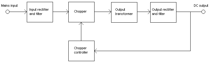
Block diagram of a mains operated AC-DC SMPS with output voltage regulation.
Rectifier stage[]
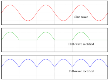
AC, half-wave and full wave rectified signals
If the SMPS has an AC input, then its first job is to convert the input to DC. This is called rectification. The rectifier circuit can be configured as a voltage doubler by the addition of a switch operated either manually or automatically. It produces an unregulated DC voltage which is then sent to a large filter capacitor. The current drawn from the mains supply by this rectifier circuit occurs in short pulses around the AC voltage peaks. These pulses have significant high frequency energy which reduces the power factor. Special control techniques can be employed by the following SMPS to force the average input current to follow the sinusoidal shape of the AC input voltage thus the designer should try correcting the power factor. A SMPS with a DC input does not require this stage. A SMPS designed for AC input can often be run from a DC supply, as the DC passes through the rectifier stage unchanged. (The user should check the manual before trying this!)
If an input range switch is used, the rectifier stage is usually configured to operate as a voltage doubler when operating on the low voltage (~120 VAC) range and as a straight rectifier when operating on the high voltage (~240 VAC) range. If an input range switch is not used, then a full-wave rectifier is usually used and the downstream inverter stage is simply designed to be flexible enough to accept the wide range of dc voltages that will be produced by the rectifier stage. In higher-power SMPSs, some form of automatic range switching may be used.
Inverter stage[]
The inverter stage converts DC, whether directly from the input or from the rectifier stage described above, to AC by running it through a power oscillator, whose output transformer is very small with few windings at a frequency of tens or hundreds of kilohertz (kHz). The frequency is usually chosen to be above 20 kHz, to make it inaudible to humans. Computer supplies run at 360 volts DC. The output voltage is optically coupled to the input and thus very tightly controlled. The switching is done by MOSFETs, which are a type of transistor with a low on-resistance and a high current-handling capacity. This section refers to the block marked "Chopper" in the block diagram.
Voltage converter[]
If the output is required to be isolated from the input, as is usually the case in mains power supplies, the inverted AC is used to drive the primary winding of a high-frequency transformer. This converts the voltage up or down to the required output level on its secondary winding. The output transformer in the block diagram serves this purpose.
If a DC output is required, the AC output from the transformer is rectified and smoothed by a filter consisting of inductors and capacitors. The higher the switching frequency, the smaller in value components are needed.
Simpler, non-isolated power supplies contain an inductor instead of a transformer. This type includes boost converters, buck converters, and the so called "buck-boost converter". These belong to the simplest class of single input, single output converters which utilise one inductor and one active switch (MOSFET). The buck converter reduces the input voltage, in direct proportion, to the ratio of the active switch "on" time to the total switching period, called the Duty Ratio. For example an ideal buck converter with a 10V input operating at a duty ratio of 50% will produce an average output voltage of 5V. A feedback control loop is employed to maintain (regulate) the output voltage by varing the duty ratio to compensate for variations in input voltage. The output voltage of a boost converter is always greater than the input voltage and the buck-boost output voltage is inverted but can be greater than, equal to, or less than the magnitude of its input voltage. There are many variations and extensions to this class of converters but these three form the bases of almost all isolated and non-isolated DC to DC conveters. By adding a second inductor the Cuk and SEPIC converters can be implemented or by adding additional active switches various bridge converters can be realised.
Other types of SMPS use a capacitor-diode voltage multiplier instead of inductors and transformers. These are mostly used for generating high voltages at low currents.
Regulation[]
A feedback circuit monitors the output voltage and compares it with a reference voltage, which is set manually or electronically to the desired output. If there is an error in the output voltage, the feedback circuit compensates by adjusting the timing with which the MOSFETs are switched on and off. This part of the power supply is called the switching regulator. The "Chopper controller" shown in the block diagram serves this purpose. Depending on design/safety requirements, the controller may or may not contain an isolation mechanism (such as opto-couplers) to isolate it from the DC output. Switching supplies in computers, TVs and VCRs have these opto-couplers to tightly control the output voltage.
Open-loop regulators do not have a feedback circuit. Instead, they rely on feeding a constant voltage to the input of the transformer or inductor, and assume that the output will be correct.
Power factor[]
Unlike most other appliances, switched mode power supplies tend to be constant power devices, drawing more current as the line voltage reduces. Also, in common with many static rectifiers, maximum current draw occurs at the peaks of the waveform cycle. This means that basic switched mode power supplies tend to produce more harmonics in the mains power line and have a worse power factor than other types of appliances. This may cause stability problems in some situations such as emergency generator systems or for very heavy loads on ordinary power mains (as it can lead to increased neutral current and increased heating of the utility transformers). However, higher-quality switched-mode power supplies with power factor correction (PFC) are available; these are designed to present a near resistive load to the mains. European regulatory standards are now beginning to require power factor correction and harmonic reduction.
Types[]
Switched-mode power supplies can classified according to the circuit topology.
- Buck converter (single inductor; output voltage < input voltage)
- Boost converter (single inductor; output voltage > input voltage)
- buck-boost converter (single inductor; output voltage can be more or less than the input voltage)
- flyback converter (uses output transformer; allows multiple outputs and input-to-output isolation)
- forward converter (uses output transformer; allows multiple outputs and input-to-output isolation)
- Ćuk converter (uses a capacitor for energy storage; produces negative voltage for positive input)
- Inverting charge-pump (Modified Ćuk with single inductor; output voltage negative and higher-magnitude than positive input voltage)
- SEPIC converter (two inductors; output voltage can be higher or lower than input voltage)
External articles[]
- Switching-Mode Power Supply Design
- Unitrode Power Supply Design Seminar Books Online
- Switched Mode Power Supplies. A fairly detailed discussion of converter types and control schemes. Does not cover modern switcher ICs.
- Watkins, Steve, "History and development of switched-mode power supplies pre 1987". 1998 (ed. the bibliography is here.)
- [1]. A general description of DC-DC converters.
References[]
- Robert W. Erickson & Dragan Maksimovic Fundementals of Power Electronics Second edition ISBN 0792372700 .
- Ned Mohan, Tore M. Undeland, William P. Robbins (2002). Power Electronics : Converters, Applications, and Design. Wiley. ISBN 0-471-22693-9.
- Muhammad H. Rashid (2003). Power Electronics : Circuits, Devices, and Applications. Prentice Hall. ISBN 0-131-22815-3.
- Fang Lin Luo, Hong Ye (2004). Advanced DC/DC Converters. CRC Press. ISBN 0-849-31956-0.
- Mingliang Liu (2006). Demystifying Switched-Capacitor Circuits. Elsevier. ISBN 0-750-67907-7.
- Fang Lin Luo, Hong Ye, Muhammad H. Rashid (2005). Power Digital Power Electronics and Applications. Elsevier. ISBN 0-120-88757-6.
- Abraham I. Pressman (1997). Switching Power Supply Design. McGraw-Hill. ISBN 0-070-52236-7.
| This page uses Creative Commons Licensed content from Wikipedia (view authors). | 
|