Thermal power station
A thermal power station includes all the equipment and systems that go in to make a complete thermal power station of an electricity utility company with fossil fuel steam generator or boiler, but excludes the civil connected works. Only a brief description and salient features of the items covered are added. For ease of understanding, typical schematic diagrams are also referred to.
In addition, this article, supplements the article fossil fuel power plant, which generally describes the origin, basic technology and the inventors etc. The present article describes briefly individual main items and systems based on units installed in thermal power stations of electricity generation utilities in India, by various manufacturers/consultants through out the world, based on their collaboration with Indian firms.
Part I- Steam generator unit
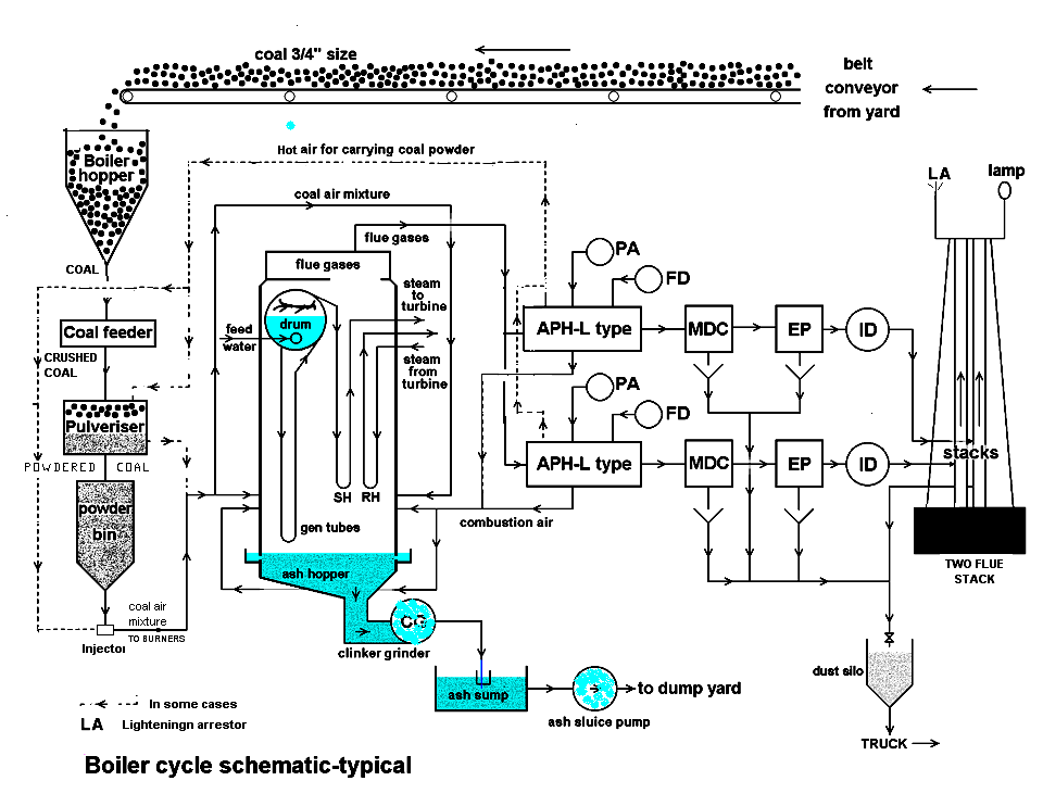
The steam generator unit has to produce steam at highest purity, and at high pressure and temperature required for the turbine. This is made up of Economizer, the steam drum with all internal and external fittings and chemical dosing arrangement, generating tubes (with necessary headers for uniform distribution of water flow) forming the Furnace chamber and superheater coils. Necessary safety valves are located at suitable points to avoid excessive boiler pressure. Air and gas path equipment are: forced draught fan (FD fan), air preheater (APH), boiler furnace, induced draft fan (ID fan), mechanical and electrical dust precipitators and the Stack or Chimney
For units of about 200 megawatt (MW) caspacity, FD fan, APH, dust collectors and ID fan are duplicated with necessary isolating dampers. On some units of about 60 MW two boilers per unit are provided instead.
Mounted equipment
The boiler furnace has mounted on it the coal nozzles and igniter guns, soot blowers, and water lancing. Necessary ports on furnace walls with safety covers for manual observation inside the furnace are provided. Necessary air vents and drains are provided on steam drum, superheater coils and headers etc. for initial start up and for maintaining the boiler water concentration.
Economizer, air preheater, etc.
External fans are provided to give sufficient air for combustion. The FD fan takes air from atmosphere and injects it through the airpreheater to the air nozzles on the boiler furnace to give hot air for better combustion. The ID fan sucks out or draws out the combustible gases from the furnace to assist FD fan and to maintain always slightly negative pressure (about half an inch or one cm of water) in the furnace to avoid backfiring through any opening. Just at the outlet of furnace and before the furnace gases are handled by ID fan, fine dust carried by the outlet gases are removed to avoid atmospheric pollution (environmental limitations prescribed by law) as well as to minimize erosion of ID fan rotors etc. The drum internals provided are such that the wet steam entering the drum from the generating tubes is removed of moisture, and then the dry steam enters the superheater coils. Furnace explosions or Boiler explosions due to accumulation of combustible gases after a trip out can be avoided by flushing out these gases from combustion chamber before starting igniters. The general location of equipment in the boiler cycle is shown in the diagram. The boilers come under the statutory inspection of Chief Boiler Inspectorate in every state in India.
Fuel preparing system
The coal crushed to about ¾ inch (6 mm) in size from the coal yard is conveyed and stored in the boiler hoppers above the boilers. The coal then passes through pipes to the coal feeders for regulating and measuring coal quantity, then to coal pulverizers for pulverizing coal, and then to a pulverized coal bin. The pulverizers may be of rotary drum type or ball or roller grinder type. In some power stations what is known as residual oil is used as main fuel. This oil congeals (becomes solid like wax) below about 50 °C due to its high content of wax, about 50%. This oil therefore is always kept above this temperature even in storage tanks to make it pumpable. For spraying into the furnace the oil temp at burner tips is maintained at about 100 °C. For all instruments on this oil line lagging or heat insulation is provided for their proper working.
This oil is transported from refinery direct by means of oil wagons provided with steam heating coils. This oil is generally loaded at the refinery at about 80 °C. The pipe line carrying this oil is lagged (insulated) at all points.
Some boilers in some power stations use natural gas also as main fuel. Gas taken out from gas wells is sent to group gathering station nearby at about 600 psi (4.1 MPa) by reducing the well pressure at wellhead by means of a Beans orifice (named after the inventor) installed in the outlet of the Christmas tree at the well head. At the group gathering station the pressure is further reduced by pressure reducing stations and the separated liquid, known as condensate (highly volatile like petrol) in petroleum industry (not to be confused with steam condensate), is stored in tanks for disposal separately. The gas at outlet of group gathering station at about 40 kgf/cm² (4 MPa) is sent to power station about 20 miles (30 km) away by pipeline, wrapped and protected for electrolytic corrosion. At the power station site the gas pressure is further reduced to about 20 kgf/cm² (2 MPa) and supplied to the electricity utility company. The gas up to the point of supply to utility is handled by a Government of India organization known as ONGC[[1]]. The gas at boiler burners is at about one half kgf/cm² (50 kPa), and separate gas burners are provided for this on the boilers.
Fuel firing system and igniter system
From the pulverized coal bin coal is conveyed by hot air injectors through coal pipes to boiler coal burners of one tier or level at an horizontal angle into the furnace to give a swirling action for powdered coal for proper mixing of coal powder and also the incoming hot air from FD fans, to give the best combustion. If the system does not have pulverized coal bin then coal powder is conveyed directly to coal burners from pulverizes. Then generally one tier is fed by one pulverizer.
To provide sufficient combustion temperature in the furnace before spraying powdered coal to catch fire or ignite, the furnace temperature is brought up by spraying and burning light oil by means of igniter oil guns. Oil is used in a fine spray, as oil can catch fire even in ambient temperature. Alternatively gas is also used for ignition instead of oil, if available in plenty. However in this case the igniter gun design differs. To ignite the ignition oil or gas, an Electric High Tension spark in the path of oil or gas is used momentarily and then the spark gun is withdrawn.
External to boiler unit
Fly ash collection equipment and disposal
Dust separators are provided immediately at the outlet of the furnace and before the ID fan. They are of mechanical type or electrical type, sometimes mechanical followed by electrical type to reduce the load on the electrical type and also may be to comply with the provisions of law. The dust normally is collected in hoppers below them. They are emptied periodically by water jet ejectors or by air suction depending on how they are further disposed off. In case of further use of this fine ash, it is generally handled dry by air and taken to a silo located at a higher level for loading the fine ash in trucks from bottom of silo. In case of these being dumped in the yard, then wet method by water jet injectors is employed.
Boiler make-up water treatment plant and storage
Since steam is taken out continuously and returned to the boiler, losses due to blow-downs and leakages have to be made up for maintaining designed boiler water quantity by means of the level gauges provided on the boiler drum. For this, continuous make up water is added to the boiler water system. Since this make up requires pure water this quality water is obtained by a Dematerialized (DM) water treatment plant. However some storage is essential as DM plant may be down for maintenance. For this purpose a storage tank is installed from which continuously DM water is drawn for boiler make up.
The impurities in water input to this plant generally consist of calcium and magnesium salts imparting hardness to the water. These salts have to be removed from the water. If hardness is present in make up water to the boiler, the salts not only form deposits on the tube water surfaces but also lead to overheating in those localities resulting in tube failures. Therefore these have to be completely removed for use as boiler make up. This is done using DM water treatment plant which gives the purest form of water.
This generally consists of cation, anion and mixed bed exchangers. The final water from this process consists essentially of hydrogen ions and hydroxide ions which is the chemical composition of pure water. The DM water being very pure becomes highly corrosive, once it absorbs oxygen from the atmosphere because of its very high affinity for oxygen absorption. The capacity of the DM plant is dictated by the type and quantity of salts in the raw water input.
The storage tank for DM water is made from materials not affected by corrosive water, such as PVC. The piping and valves are generally of stainless steel. Sometimes on top of the water in the tank a steam blanketing arrangement or stainless steel doughnut float is provided to avoid contact with atmosphere. DM water make up is generally added to the boiler/TG cycle at the steam space of condenser, i.e. vacuum side. This arrangement not only sprays the water but also DM water gets deaerated, with the dissolved gases being removed by the ejector of the condenser itself.
The boiler and turbine generator, steam and water cycles are shown in the schematic diagram. This also shows the DM water make connection to the condenser steam space. From condenser the condensate extraction pumps pump the condensate through LP feed heaters to deaerator and then it drops to feed tank. From feed tank the feed water is pumped by feed water pumps, through the HP feed heaters to the boiler through economizer.
Fuel transport to site and fuel storage
Most thermal stations use coal as the main fuel. Raw coal is transported from collieries to a power station site by railway wagons only. Generally coal wagons are sent as a full railway rake. The coal received at site by wagons may be of different sizes. They are unloaded at site by rotary dumpers or side tilt dumpers to tip over conveyor belts below. They are generally carried direct to the crusher house for crushing the coal to about ¾ inch (6 mm) size and then by belt conveyors to storage yard. Normally this crushed coal is stored with compaction by bulldozers, as compacting of highly volatile coal avoids spontaneous ignition. Hence this arrangement is generally adopted.
The crushed coal from storage or after crushing direct is conveyed to top of boilers by means of belt conveyor system. At the top of boilers a horizontal conveyor with distributing arrangement for feeding to any boiler bunker will feed the coal to the required boiler bunkers generally which ever boiler is in operation. This is to avoid long hours of storage in boiler bunkers to avoid spontaneous ignition at that point.
Sampling for analysis
Automatic and fixed arrangement is made at the rotary dumper for getting a representative sample from each wagon. This is crushed, sieved etc. automatically and sent to local laboratory. This method takes coal only from particular portions of each wagon. Some suppliers, having come to know of this, may try to load each wagon in such a way to get always good quality sample. This has to be guarded.
Bottom ash collection and disposal
At the bottom of every boiler a hopper has been provided with a sealing arrangement with water between boiler furnace and this hopper. This is to give a seal against slightly negative pressure maintenance in the furnace and also for the expansion of the furnace walls downwards on furnace heat up. This hopper is always filled with water, overflowing continuously at the top seal to quench the ash and clinkers falling down from the furnace. Some arrangement to crush these clinkers, then for removal outside and conveying to ash dump yard is made. In some designs clinker crushers are provided submerged in water to crush the clinkers and then convey the crushed pieces by means of hydraulic jets. For long distance disposal, ash sluice pumps are also provided for conveying to ash yard. In another design the clinker crushers are provided outside submerged in water with clinker inside the hopper being removed by chain conveyors.
Others
Monitoring and alarm system for boiler unit
The boilers and connected systems do require prechecking for start up during the first start or after a shut down for any reason whatsoever. The safety aspects and the normal procedures have to be looked into at all stages of operation. Manual intervention is also unavoidable; however, much the system is made automatic. In view of this necessary protection, monitoring with alarms for out of limit parameters, and auto and manual control equipment are provided on the operators’ console, both on mechanical and electrical equipment. The control room for dust collectors, ash sluicing and other equipment is provided in separate control rooms nearer to each of them.
Battery supply emergency lighting and communication
Central battery system consisting of lead acid cell units to make up 240 V DC, sometimes in two individual stacks with its own battery charging unit, inverter to get 230 V AC, and auto-stepless changeover in case station supply of 230 V AC fails. The batteries are installed in separate rooms (battery rooms) with exhaust fans and all round coated with anti-acid proof paint (Battery room#Design Issues).
The essential equipment supplied by this battery system are: control and relay equipment, communication and emergency lighting, and turbine lube oil pumps. This control equipment is installed in separate rooms with monitoring on the operators’ console. This is essential for smooth and damageless shutdown of the units. This system generally caters all the TG units and the steam generator units.
Major problems that may occur
Furnace explosions
Sometimes furnace explosions do occur due to wrong operations involved. In this case the boiler may suffer a very bad shock and even stay girders may get bent. In addition there may be good number of tube ruptures. This will result in the whole boiler stoppage.
As a temporary measure all boiler tubes can be checked for thinning out and ruptures, at all surfaces, for their full lengths. Thinned out portions can be removed and new stubs could be welded. The remaining tubes bent due to explosion could be left as they were. With minor repairs to the stay girders the boiler could be lighted up with all precautions including uniform expansion all round, leakages from tubes etc. This emergency repair could be done if grid supply is starving. The boiler thus could be run for a year without any problem. This short gap arrangement is suggested as it may take about a year to get the new girders and tubes etc. to make a permanent repair.
This stop gap procedure however is not always recommended
Oil contamination of complete cycle
Due to a wrong operation large amount of oil may get sucked into the turbine boiler cycle during normal operation of the unit. This is indicated by all drains showing foaming. This also indicates that impure steam and condensate is circulating through the system... The unit has to be taken out immediately.
For rectification of this condition the boiler has to be given several times alkaline boil out (a normal practice). If on starting, if the drains at all points still show foaming, that indicates that the complete boiler turbine cycle had got contaminated and required thorough flushing.
The flushing of the complete boiler turbine cycle can only be done by running the boiler and turbine on low pressure steam and turbine at lower speed. During this process all the drains in the system had to be kept open. These have to be continuously monitored for clear and pure condensate by lab tests. After obtaining the required purity only the boiler pressure has to be raised slowly, continuously lab testing the sample at all drain points for clear and pure condensate. In addition, the speed of TG unit has to be simultaneously raised to normal speed.
The system thus is expected to come back to normal. This may take days or several hours.
References
External links
Part II- Steam Turbine Generator unit (TG unit)
Steam turbine generator unit (TG unit) (Steam turbine)
The '’’steam turbine generator units’’’ are provided with auxiliary systems to make it work not only satisfactorily but also safely too.
The following auxiliary systems are generally provided by various manufacturers depending on the size of unit and construction details. The list herein also shows what is normally provided for large units, of the order of about 200 MW, depending on the type of construction of the main components.
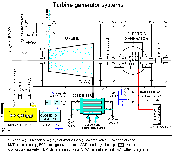
The typical line diagram also shows the different auxiliary systems.
The TG unit being rotating equipment has generally a fairly heavy and large diameter shaft. The shaft therefore requires not only supports but also has to be kept in position while running. Further they should offer less resistance (friction) for rotation. Therefore the shaft is provided with number of bearings, Fluid bearing corresponding housings and supports, depending on the construction adopted by each manufacturer. The bearing shells, in which the shaft rotates, are lined with material with low friction, like Babbitt metal.
To make the friction between shaft and bearing surface as much less as possible and to keep down the heat generated, oil lubrication is used. Therefore bearing oil system with pumps, monitoring and control equipment are incorporated.
The sketch shows a typical oil system. Normally the oil system is such that the TG unit can be started on its own without any assistance from grid or other units.
One fairly large oil tank is provided for not only storage of oil but also for locating the oil pumps needed. The oil pumps are generally vertical type, motor on top of the tank and pump themselves submerged, to make pumps more reliable. Since there are other systems requiring this oil, this oil tank is made as a common oil tank catering other oil requirements as well.
From this oil tank storing hot oil, oil is supplied to bearing and seal oil inlets through duplicate water cooled oil coolers. The oil outlet temperature at the coolers outlet is maintained at about 28°C. (Not shown in the above diagram).
From this oil tank, also a continuously operated oil filtering system is provided to remove traces of water and extraneous particles collected in the systems, as these are detrimental to these seal oil and bearing oil systems. (Not shown in the above diagram).
The bearing oil itself has requirements for normal operation, emergency operations and shut down conditions. During normal operation of the TG unit the oil pump is driven by the turbine shaft itself, taking suction from the oil tank. For starting of the TG unit, an Auxiliary Oil Pump (AOP) is provided. In emergencies when AOP is not available, a DC driven oil pump is provided in such a way that it takes over automatically when the lube oil pressure falls down to a particular level due to any reason whatsoever. However the DC oil pump cannot cater for the hydraulic system. Hence DC pump is only for lubrication and seals, when the AOP and main oil pumps are not available due to any reason whatsoever. The unit cannot be started in this condition. Some manufacturers provide therefore two auxiliary oil pumps.
The bearing oil not only acts as a lubricant but also as a cooling medium. The hot oil coming out of the bearings generally drains to a sump below the bearing housing. Each of the pipes coming out is connected to a drain pipe header leading to the oil tank inside, where it falls on a strainer basket to remove any foreign particles. The drain pipe header sometimes is enclosed in another casing for fire protection purposes.
An auxiliary oil pump (AOP) is provided for start up operation. Main oil pump driven by the turbine shaft takes over automatically when the TG shaft comes to near about full speed. In case of emergency, due to any tripping of TG unit (with AOP not coming up) the DC oil pump will start, to supply oil to bearings at a predetermined fall of lube oil pressure. The auxiliary and main oil pumps also supply the hydraulic oil for governing control but the DC oil pump is only for Bearings and generator seals.
In general all oil pumps are submerged in lube oil inside the tank. This also gives them positive suction to increase their reliability.
Barring gear
Barring gear is the term normally used for the complete mechanism provided for the rotation of the turbine generator shaft at a very low speed (of the order of one revolution per minute) after unit stoppage for to any reason. The requirement for this is very important for all capacities of turbine generator units. Once the unit is "tripped" (i.e. the turbine stop valve is closed cutting off steam to the turbine) the unit starts slowing down (also known as "coasting down"). When it reaches a dead stop, if it is allowed to be in one position for some time there is a tendency for the turbine shaft to deflect or bend.
This deflection is because of the heat inside the turbine casing tends to get concentrated in the top half of the casing, thus making the top half portion of the shaft hotter than the bottom half. The shaft therefore warps or bends by millionths of inches, only detectable by monitoring meters such as the eccentricity meter on the operators’ console.
But this small amount of shaft deflection would be enough to cause vibrations and wreck the whole turbine generator unit when the huge mass started spinning. Even the whole concrete building vibrating has been observed in some cases where barring was not used. Therefore the shaft is not allowed to come to a dead stop, but a mechanism known as turning gear or barring gear automatically takes over to rotate the set at a particular set low speed.
If the unit has to be taken down for major maintenance requiring inspection of turbine bearings, etc., then barring gear has to be kept in service till the temperatures of the casings and bearings, as seen on the operators’ console, are sufficiently low as prescribed by the manufacturers.
The barring motor supply is therefore taken from a reliable source. In very small units of capacities of the order of about 500 kW and below, the mechanism may be hand operated to change the shaft position by 180 degrees frequently. This is done using a bar temporarily attached to the shaft—hence the term "barring".
All the necessary monitoring instruments such as turbine casing temperatures, shaft eccentricity meters, vibration indicators, etc. with alarms for various operating limits, are provided at operators’ console, in addition to starting and stopping controls.
Auxiliary oil system
This system with auxiliary oil pump (AOP) is designed for supplying oil at the start up of TG unit. The oil pump is designed to supply the hydraulic oil system consisting of Turbine stop valve in the main steam line to turbine, the governing control valves, the bearing and seal oil systems and relevant hydraulic relays and other mechanisms.
At about a predetermined speed the turbine main shaft driven pump takes over the functions of the AOP and then AOP is stopprd manually. Some units have a stand by AOP to automatically take over if first one fails during start up due to defective conditions. The pump casings are submerged in oil so that they have always positive suction to make them more reliable.
seal oil system, hydrogen cooling system and stator cooling water system
The generator coupled to the turbine does require some arrangement for cooling to dissipate the heat generated inside, depending on the size of the unit. Though in small size units it is mostly natural air cooling through air filters at inlet, in larger units generally found in power generating utilities now a day, special closed circuit cooling arrangements are incorporated. The one shown in the typical diagram has hydrogen gas cooling in the generator casing and stator coils are hollow to take water cooling. The Hydrogen gas is used because mainly of its higher affinity for heat absorption, lowest density to give less friction in a rotating medium, and being non self igniting. However it should be noted that Hydrogen gas is explosive in presence of air. The hydrogen pressure therefore is maintained slightly higher than atmosphere pressure say at about 1.5 kgf/cm² (150 kPa), to avoid outside air ingress. Due to this higher pressure than outside pressure, to avoid leakage to outside atmosphere where shaft emerges out of the casing, some form of sealing arrangement has to be provided.. This is done by providing mechanical seals round the shaft with a very small annular gap in-between to avoid rubbing between shaft and seal. To avoid gas leakage from this very small annular gap and also to avoid heat generation beyond limit, oil under pressure is provided in such way that part of the oil flows to inside and part to outside. The oil flowing inside prevents the hydrogen gas leakage to atmosphere.
This oil is called seal oil and should always be present as long as gas pressure inside is above atmosphere. Some manufacturers provide Carbon rings in housing as seal and some others provide other types known generally as labyrinths. The seal oil entering the seal oil housings is therefore split in to two parts one going inside the casing and the other coming out. The coming out oil is taken to bearing drain itself. The oil going inside the casing, which is under pressure, requires some sort of seal system to remove this oil to outside of casing as no oil should accumulate inside the casing, having conductors stressed to high voltage. Different makers have their own designs for removing through a loop seal arrangement.
Since hydrogen gas is explosive with atmospheric air under certain conditions, a system has to be incorporated for its handling. For the first filling of hydrogen, purging out of the same for any inspection inside, for normal make up for losses during running and to maintain desired pressure and purity continuously, a separate system is provided. Also firefighting arrangement for inside generator explosions is incorporated with monitoring and control equipment. This system includes hydrogen gas cylinders and carbon dioxide (CO2) gas cylinders suitably located with pressure reduction stations and piping to the generator casing, and purging piping. All purging pipe connections are lead to open air at highest level to dilute the purged gases to avoid explosions.
Some power stations have hydrogen generation plants at site to avoid long distance transport of a large number of cylinders.
The generator conductors are made hollow to take water for cooling to remove further heat from coils. The generator coils being at about 22 kilovolts (kV), and water being conductive with and from safety point of view, some form of insulating barrier material (such as Teflon tubing) is used for interconnection of cooling water line and the generator HV coils. The DM water of lowest conductivity and without any impurities is used for passing through the coils. The DM water used for this purpose is in a closed circuit, because of its affinity to absorb oxygen from the atmosphere and make it highly corrosive. It is also provided with its own mixed bed ion exchangers and magnetic and mechanical filters to maintain highest purity and free of any foreign material, though it takes DM water from the station DM plant unit for initial charge and small make up.
Generator excitation system
The generator requires DC excitation current, it being an alternate current generation. During the 1960s the turbine generators were generally provided with a separate main-shaft driven DC generator, known as exciter, and some times another exciter known as pilot exciter is provided for better regulation of generator output. Nowadays, due to further technology developments instead of DC generator, an AC generator is provided with incorporated rotating rectifier assembly, with external electronic control of the DC output to the main AC generator. The heavy DC current leads for the main generator are taken directly from this AC rotating exciter. This system has more advantages and reliability. It mainly avoids the cumbersome voltage regulator provided at the control room and the connecting heavy DC leads. Even small diesel fenerator units are now provided with this system. The electronic controls are installed in a separate room and require very little attention.
Generator high voltage system
The Generator voltage is normally 11 kV in smaller units and in bigger units it would be about 22 kV. Probably this is limited by the insulation media available and the construction methodology limitations available today. The generator HV leads are normally of large section aluminum channels because of very high current as against cables used in smaller machines. They are enclosed in aluminum bus ducts (with good grounding), live channels being supported on suitable insulators inside. Further the generator HV channels (leads) are directly connected to suitably designed step-up transformers for connecting to a transmission yard high voltage substation, of the order of 110 kV or 220 kV for further transmission by grid. The HV generator channels generally being of long run and also subjected to heat and cold, necessary suitable expansion joints are also provided.
The necessary protection and metering devices are incorporated on the HV leads of generator. Thus the TG unit and the transformer form one unit. In smaller units, generating normally at 11 kV, a breaker is provided to connect it to a common 11 kV bus system in a cubicle located normally indoors. In this case the TG unit by itself, becomes a unit.
Others
Monitoring and alarm system for the TG unit
The TG units do require prechecking for start up during the first start or after a shut down for any reason whatsoever. The safety aspects and the normal procedures have to be looked into at all stages of operation. Manual intervention is also unavoidable however much the system is made automatic. In view of this necessary protection, monitoring with alarms for out of limit parameters, and auto and manual control equipment are provided on the operators’ console, both on mechanical and electrical equipment.
Major problems that could be experienced
About 50 years back computer control for power station equipment was not available. For the reliability of power supply to consumers, they have to depend purely on the skill of the engineer in charge of the power station and his staff.
Problem on condensers
One of the problems on condensers of steam turbines is on tubes. The condenser tubes if made from aluminum brass (otherwise called Alumbro), due to its cheapness, may start failing in hundreds per day (generally termed catastrophic failure) after about some period of operation. A detailed investigation may show that this is due to stress corrosion cracking. This in turn may be attributed to high PH steam entering turbine condenser from turbine. Which in turn may be attributed to high concentration in boiler water maintained due to carry over from make up water. If the make up is from evaporators only, then the purity cannot be to that extent as given by the purity by DM water treatment plant.
This problem can be solved by replacing all the condenser tubes by Cu-Ni tubes and changing over to DM water.
Maintenance on turbine proper
If high TDS (total dissolved solids) from boiler water is carried by steam, then the turbine blades etc internally get hard and soft deposits of salts. One of the methods to get rid of the deposits without opening turbine in an emergency is to do turbine washing with low pressure wet steam. This can be done with turbine on low speed with low steam pressure and that too wet steam. This may give some cleaning as an emergency method. As a permanent method the only way left is to open the casing and mechanically clean inside.
The testing for leaky tubes has to be done very fast, as it involves large number of tubes. This can generally be done, that too on half side, generally in the night due to lower loading on the power station. With half condenser operation and with a small gadget such as simple U tube water manometer with coloured water, unskilled workers can be used to find out the leaky tubes very fast and plug them too.
References
External links
| This page uses Creative Commons Licensed content from Wikipedia (view authors). | 
|